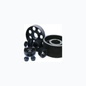
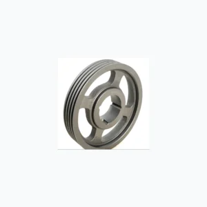
For a 10-groove SPC drive, this series page is the dimensional working sheet. It spans P 250–1250 mm and uses bush references 4040, 4545, 5050; the correct row is chosen from the machine ratio, shaft diameter, available axial space and the construction type shown for that row.
The SPC profile is 22 × 18 mm. In procurement language the same component may be called a V-belt pulley or sheave; keep the belt section unchanged unless the whole drive is being redesigned.
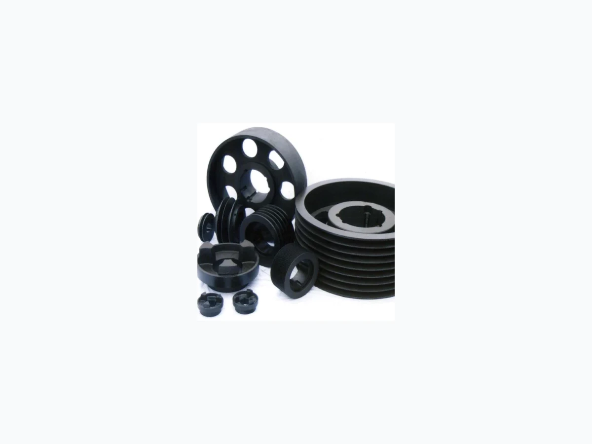
SPC ten-belt specifications
Use the complete table below to identify the exact EP- model. It retains 14 dimensional rows rather than creating a separate near-identical sales page for every diameter.
| EP Model | P (mm) | O (mm) | Type | Bush | Max Bore (mm) | E | F | J | K | L | M | N |
|---|---|---|---|---|---|---|---|---|---|---|---|---|
| EP-SPC 250-10 | 250 | 259.6 | 3 | 4040 | 100 | - | 264 | 196 | 81 | 102 | 84 | - |
| EP-SPC 280-10 | 280 | 289.6 | 3 | 4040 | 100 | - | 264 | 226 | 81 | 102 | 81 | - |
| EP-SPC 300-10 | 300 | 309.6 | 3 | 4545 | 110 | - | 264 | 245 | 75 | 114 | 75 | - |
| EP-SPC 315-10 | 315 | 324.6 | 3 | 4545 | 110 | - | 264 | 258 | 75 | 114 | 75 | - |
| EP-SPC 355-10 | 355 | 364.6 | 3 | 4545 | 110 | - | 264 | 299 | 75 | 114 | 75 | - |
| EP-SPC 400-10 | 400 | 409.6 | 3 | 5050 | 125 | - | 264 | 342 | 68.5 | 127 | 68.5 | - |
| EP-SPC 450-10 | 450 | 459.6 | 6 | 5050 | 125 | 40 | 264 | 394 | 68.5 | 127 | 68.5 | 245 |
| EP-SPC 500-10 | 500 | 509.6 | 6 | 5050 | 125 | 40 | 264 | 444 | 68.5 | 127 | 68.5 | 245 |
| EP-SPC 560-10 | 560 | 569.6 | 5 | 5050 | 125 | - | 264 | 504 | 68.5 | 127 | 68.5 | 245 |
| EP-SPC 630-10 | 630 | 639.6 | 5 | 5050 | 125 | - | 264 | 574 | 68.5 | 127 | 68.5 | 245 |
| EP-SPC 710-10 | 710 | 719.6 | 5 | 5050 | 125 | - | 264 | 656 | 68.5 | 127 | 68.5 | 245 |
| EP-SPC 800-10 | 800 | 809.6 | 5 | 5050 | 125 | - | 264 | 737 | 68.5 | 127 | 68.5 | 245 |
| EP-SPC 1000-10 | 1000 | 1009.6 | 5 | 5050 | 125 | - | 264 | 937 | 68.5 | 127 | 68.5 | 245 |
| EP-SPC 1250-10 | 1250 | 1259.6 | 5 | 5050 | 125 | - | 264 | 1187 | 68.5 | 127 | 68.5 | 245 |
How this groove count changes selection
Treat the model row as an interface record. P controls the theoretical ratio; O affects physical clearance; the bush and maximum-bore entries constrain shaft fit; E/F/J/K/L/M/N describe the remaining construction dimensions that may matter to a replacement.
Typical application discussions for SPC include large process machinery, heavy pumps, compressors, crushing and mineral-processing auxiliaries. For this ten-belt arrangement, heavy drive layouts that require careful shaft, hub, alignment and guarding checks; final belt capacity and shaft loading still need to be checked against the actual machine duty.
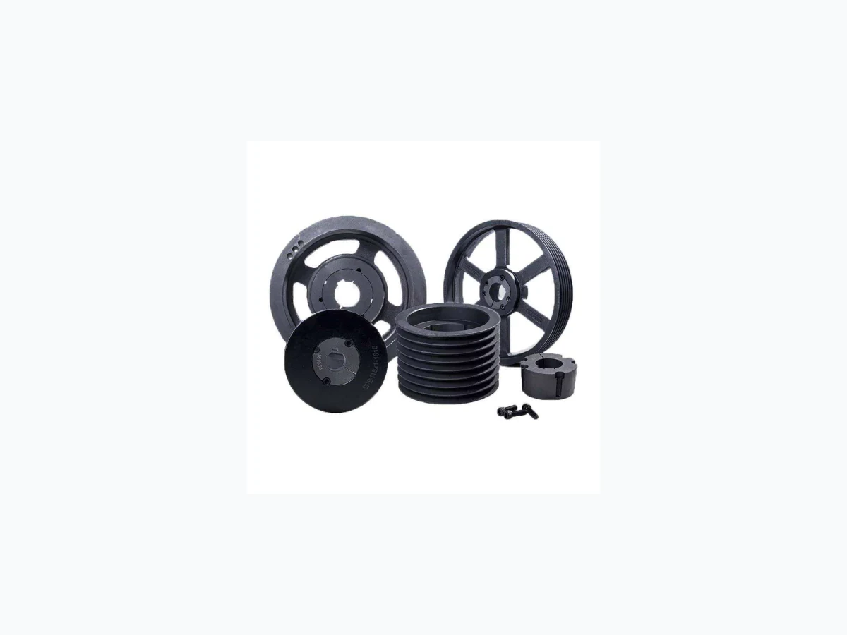
Installation and replacement focus
A wider or narrower pulley bank changes more than belt count. Re-check axial space, key position, shaft shoulder clearance and guard width before installation, and inspect the full belt set for uneven wear that could indicate an alignment problem.
Identify
Read the SPC belt marking and count the grooves before measuring the pulley.
Calculate
Use pitch/datum diameter for speed ratio; use outside diameter for space checks.
Confirm
Match shaft diameter, bush, key arrangement and the row-specific construction dimensions.
Questions to resolve before an RFQ
Which model row should I quote?
Quote the EP- designation whose P/O dimensions, groove count, bush and bore range match the machine. Add the shaft diameter and existing marking if it is a replacement.
Can another groove count be substituted?
Changing groove count changes pulley width and belt capacity. Treat that as a drive-design change rather than a direct replacement.
What if the old marking is unreadable?
Send belt markings, groove count, shaft size, photographs and measurable diameters/widths so the interface can be narrowed down.
Quote the exact row, not only the family
Send the selected EP- model, shaft diameter, driver and driven speeds, application and any drawing or replacement reference to [email protected].